Dangerbot (side view)
Here is Dangerbot 1. He is the first Fred Head that I built. The base is a lid from a prescription
bottle and the ribbed stuff wrapped around it is part of an old printer drive belt. You'll notice I
repeated this decoration on the plastic bubble above the motor as well.
Dangerbot (front view)
I've noticed that the fred head circuit is sometimes prone to random movement. He will
turn away from light and eventually be facing away from the source of light. Upon
further investigation, I found the reason to be that the red LED's used have
a kind of magnifying lens end on them (like most LED's do) which focuses the light inside the LED.
This effect makes Dangerbot predictable only if the light is in nearly a direct line with the
LED. Since I designed Dangerbot to be a desk ornament of sorts, this was OK.
When I made a Dangerbot for my brother, I also made up a complete and detailed instruction
booklet which is available
HERE as a PDF. If you're
considering building a FRED Head style robot, this is a must read guide with lots of good information
on tuning this type of circuit.
Dangerbot's Brain (detail)
Here is Dangerbot's "brain". When I was designing him I didn't have any idea for a name. That came to me like lightning later!
Notice how the "brain" kinda looks like the robot from "Lost in Space"? AH HA!! "Danger, Danger
Will Robinson!!" Do ya get it? If not, watch the show. Any good robot enthusiast should watch at
least a few episodes. Anyhow, the plastic bubble was from a bubble gum machine thing that gave out
the small plastic egg-like containers with cheap jewelry and whatnot in them. Upon inspection I
noticed that the egg fit perfectly over the motor. Between the motor and the brains there is a small
encoder disc that I got in a grab bag of stuff and shaved it down to fit. I used double-sided foam servo
mounting tape to attach the brain, disc, and the solar panel. For more information on my commonly used
assembly techniques, please visit my
Techniques section!
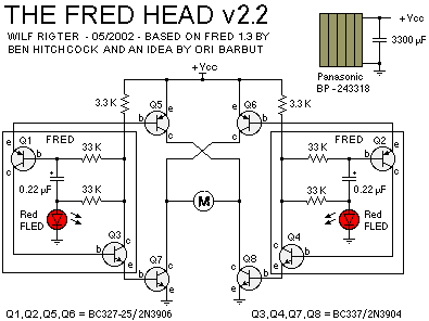
Here's the Schematic
Dangerbot is based on the Fred Head v2.2 Schematic above.
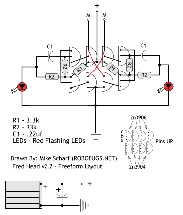
Here's My Freeform Layout
This is a Layout for the Fred Head v2.2 that I designed in Xara X. Xara is a fantastic vector based
graphic design program. The power storage capacitor on Dangerbot is a 6800uF 16v Electrolytic.
It was much too heavy for use on a roving bot but just the ticket for Dangerbot. The capacitor was
positioned to balance the weight of the motor.
Below is another Dangerbot I built. I gave this one to my brother as a Christmas gift. The electronics are
identical to the first Dangerbot. The only real difference is the base is an old 333Mhz computer processor
I salvaged. It looks really cool and compliments my brother's outstanding acheivements in computer
programming and computer science. I'll leave you with a few more photos of this Dangerbot before we move
on. Enjoy!

.jpg)
2.jpg)
.jpg)
.jpg)
.jpg)
.jpg)
.jpg)
.jpg)
.jpg)
.jpg)