Ticker
This is Ticker! He's the latest addition to my growing collection of BEAM Robots. Ticker is a Photovore, which
simply means he "eat's" light. I completed him in early June 2004. The framework of Ticker was my first attempt
at constructing a robot using brass components soldered together.
Ticker got his name for two main reasons. First, time ticked away looking at my modified kitchen timer gearboxes
for close to a year before deciding what to build with them. The other reason for his name is because of the
sound the gearboxes made when they were in the kitchen timers. He still makes a kinda tick sound when he moves,
although not as sharp and defined as a kitchen timer.
 TN.jpg)
Ticker (side view, wheel off)
In this photo you can see the overall mechanical layout of the robot. Notice how the plates that
make up the gearbox are a funny shape. They were round when I started. I carefully picked out the
gears that would be required for the design while removing all excess material and gearing. The
next task was to try to find a way to connect 2 of these modified units to each other for use in a
robotic platform. It took some time, but the results were worth it. The gearboxes work pretty good
considering they were only 2 dollars each!
 TN.jpg)
View from Above Rear
In this photo, you can see the motor attatched to the gearbox. Notice the small gear on the
output shaft of the motor. This little thing was a very large gear with this little "baby" gear molded
on it too. I used a Dremel to carefully remove all the material except for the small gear. The motor
was selected, not for size or power, but for the output shaft diameter. It fit perfectly and snugly
into the small plastic gear where the axle goes. To support the far end of the gear, I used a piece
of the original axle that was in the gear.
 TN.jpg)
Gear/Motor Close-Up
The motor has a paperclip tightly wrapped around it to hold it. This is because that the heat produced
when soldering to a motor this small will ruin it. Setting the gear mesh is also important. It directly
affects the current draw and efficiency of the gear system. You can usually tell by the sound how efficiently
it's running, but always double check current draw using a multi-meter. Try to get your gearbox to draw as
little current as possible under no-load to ensure maximun efficiency.
 TN.jpg)
On Ticker's belly, you can see the electronics that make him work. Starting at the top, we can see the two
brown rectangular capacitors. These are timing capacitors which determine how long the motors run on each
burst of energy before stopping to recharge again. Nestled under the resistors (red striped thingys) are
the transistors and voltage detectors. If you look closely at the 2 big black wires next to the big red power
wire, you can just barely see where they go inside the tubular body. They re-emerge near the front and connect
to the eyes. The flat butter knife shaped thingy near the wheel on the right is the centering adjustment. This
is the only adjustment on this robot. It is how I tune the robot to go straight towards light. The silver
barrel is the main power storage capacitor. It acts like a battery of sorts, charging and discharging whenever
the robot is in light. The silver ball on the very bottom is the tail end of Ticker. It's just a ball I had lying
around that I soldered onto the end. It acts like a "wheel" although it doesn't turn, it just slides along.
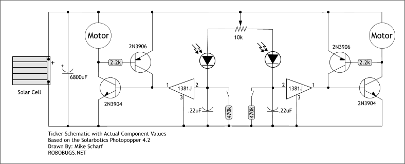
Ticker's Schematic
Those of you "in the know" should quickly recognize this schematic! It's the very popular 1381 Photopopper! If
you're in need of some circuit explanation, there are a couple of places to visit. First is
Solarbotics Photopopper 4.2 Kit Instructions. This
is a good paper to read which covers alot of ground in a very nice layout. It is mainly intended for the Solarbotics
Photopopper Kit, but Ticker uses this very same circuit. If you'd like an excellent tutorial on how to build your very
own Photopopper, check out
Chiu-Yuan Fang's "How To Build A Photovore" page.
This is the definitive page for building a very compact, freeformed (no circuit board) photovore. It also has a very
handy Troubleshooting section at the end of the page!
 TN.jpg)
Ticker Top View
Here you can get a better idea of the layout of Ticker. The brass rectangle at the top end of Ticker is
part of a shield which partially covers his eyes. This helps keep him from having direct light on both
eyes and confusing him. It helps to divide his vision to decide to go either one way or the other to
get to the brightest area.
Above Front
Here is a little better view of that shield. I may use this space to add an additional solar panel
in the future. Especially if I ever end up putting Ticker on display somewhere. He's already very
active with one panel, but with two he would be REALLY active!
 TN.jpg)
 TN.jpg)
Here's a couple of full frontal views of Ticker. Notice how he's pretty symmetrical? This is a
feature of all living things. One more thing I'd like to point out is the wheels. These wheels
are from 1988 or 1989 when I was in shop class. We had made CO2 powered cars on wood shop and
had a race with them. I won, of course, but these were the wheels from that car. Amazingly, they
lingered around my "stuff" collection and became the exact perfect item for Ticker! Another case
of time just "ticking away" on some of the parts used in his construction. The treads on the wheels
are actually the rubber feet from an old turntable. I simple cut away everything but the knurled part
off the feet, and then slid it onto the plastic wheels. Perfect Fit!
Well, that's the story of Ticker! I'm off to the bench to ponder other projects now!

.jpg)
.jpg)
.jpg)
.jpg)
.jpg)
.jpg)
.jpg)
.jpg)
.jpg)
.jpg)