My First Fred Photopopper
This is the first Fred photopopper I ever built. I used a tutorial from a site called "Andy's Light-seeking Robots"
to build Fred. The tutorial I used is
HERE and another
excellent one posted more recently by "Ray's BEAM Bots" can be found
HERE
in case you too would like to build your own Fred Photopopper. I am actually going to feature both of my Freds on this page because they're almost
identical except for the size of the power capacitors. This Fred uses a 3300uF 6.3v cap while the one pictured below
uses twin 2200uF 16v caps.
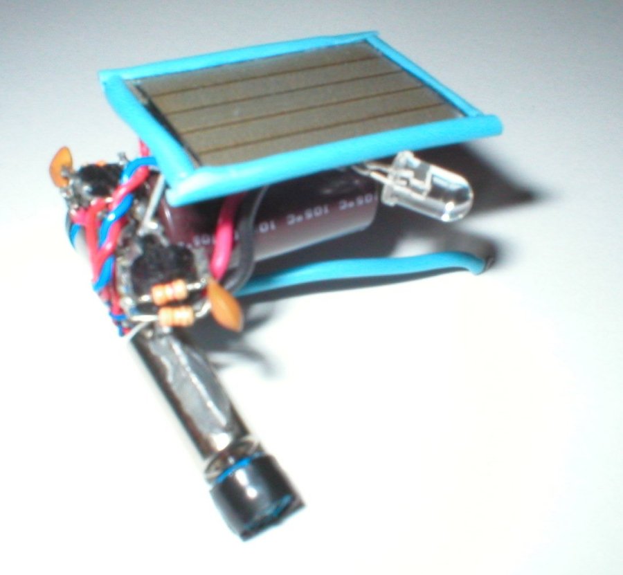
My Second Fred Photopopper
When I built this Fred I was trying to make him look a little more Pleasing to the eyes. I used black and blue wires
and heat shrink to give him a color theme. The wheels are little rubber pinch rollers from a micro-cassette mechanism.
Fred 1 (underbelly)
In this photo you can see the paperclip that the Solar Cell has been attatched to. I used servo tape
as described in the
Techniques section.
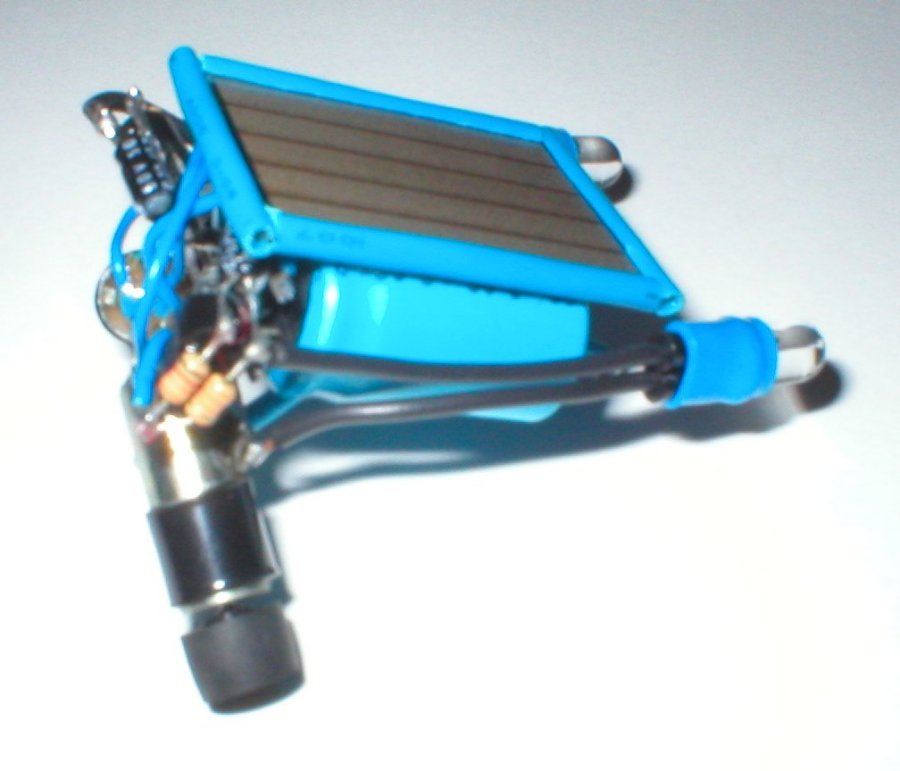
On this Fred the solar panel was mounted with servo tape directly to the capacitors. On both robots,
the solar panels are firmly mounted. Also on these bots you can see I make the eyes flexible by using
solid hook-up wire to mount the FLED's. That is especially nice for tuning or adjusting these to suit
their habitat. The eyes can be tucked under the solar panel to make the bot respond better to shadows or,
they can be extended to make the bot follow direct light. These adjustments make for a robot with an
adjustable personality of sorts.
Below are a few side by side comparison photos for your enjoyment!
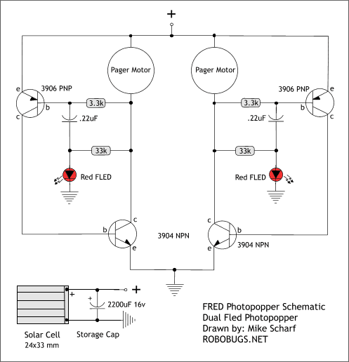
Here's the Schematic
On my robots there were some different values substituted. The storage cap and the small capacitors. On Fred 1
I used a 3300uF 6.3v storage cap and the small caps were .033uF. On Fred 2 I used twin 2200uF 16v storage caps
and the small caps were .22uF 50v Electrolytic pieces. The values shown in the schematic are the ones used in the
tutorial. They can usually be adjusted to suit your parts supply provided that you breadboard and test your
circuit before assembly. I got good results with both of my bots using many different values.

.jpg)
.jpg)
.jpg)
.jpg)
.jpg)
.jpg)
.jpg)
.jpg)