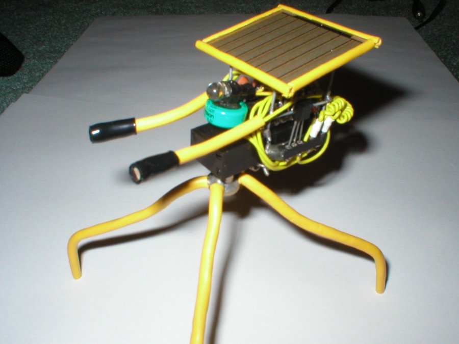
Here is Ole Yeller! He's my first power smart head. This robot has alot of unique features.
The solar panel is attached using solder pads glued to the back of it as discussed in the
Techniques section. The 1381 Voltage Trigger is easily swapped
to a different value using a plug-in section on the side of the robot. The motor was very expensive
and so I made it removable also.
Ole Yeller Disassembled
This is what Ole Yeller looks like after being disassembled. Notice a few things. First, the legs are
removeable using a small allen key. This makes storing and transporting Yeller a breeze. The motor is
held in place by springs on the frame. The motor connectors are pins from an IC socket. The socket was
a high reliability piece with the round shaped holes in it. I coiled the wires for looks and because every
robot should have them. The eyes are photoresistors and are easy to re-position. The legs are house wiring
covered with yellow insulation taken from automotive wire.
Ole Yeller Under the Hood
Here you can easily see the springs hanging on to the motor by squeezing it. I found that by slightly melting
a small spot on the motor case where the frame touches it helps to align the motor properly when re-assembling
the bot. I slide the motor straight forward to remove it. This motor is a super low power "escap" precision
gearmotor from
Solarbotics and so I wanted to be able to use it in
more than one robot. By using the quick-connect motor leads and this spring mounting system, I can use it in
other bots by just making another frame to build on. The solar panel is mounted using a method described in the
Techniques section. This makes it easy to get to the 74HC240 brains and make
tuning adjustments or repairs when necessary. It also allows the panel to be moved onto another robot if the
need arises.
Left Side View
In this photo, notice the plug-in strip on the side. The 1381 voltage trigger is easily accessible as are the
motor leads.
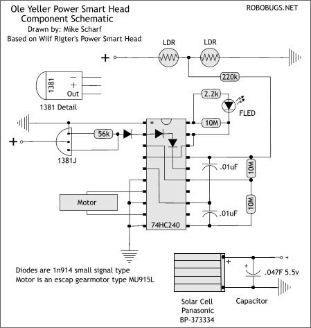
Ole Yeller's Component Schematic
This is a component schematic of the circuit I used in Ole Yeller. I say Component Schematic because it isn't
a usual schematic but more like a freeform layout drawing. If you wanted to you could actually use this type
of schematic to build a freeform version of this circuit because the components are represented as they truly
are. This circuit is actually a Power Smart Head by Wilf Rigter. It is an interesting circuit in that when
it's locked on to a light source it draws almost no power. It can actually charge the cap when locked on. When
tracking a light source, the escap motor draws only about 5ma and the rest of the circuit almost nothing. The
only downside to this circuit is the eyes (LDR's). The Light Dependent Resistors are connected directly across
the power supply. This actually loads the power supply at all times and gets worse as the light on the LDR's
gets brighter. There are other ways of making the eye's including using photodiodes, phototransistors, or small
solar panels that would eliminate the loading problem. For a complete round-up of power-smart heads see Wilf
Rigters article BEAM Heads 101.
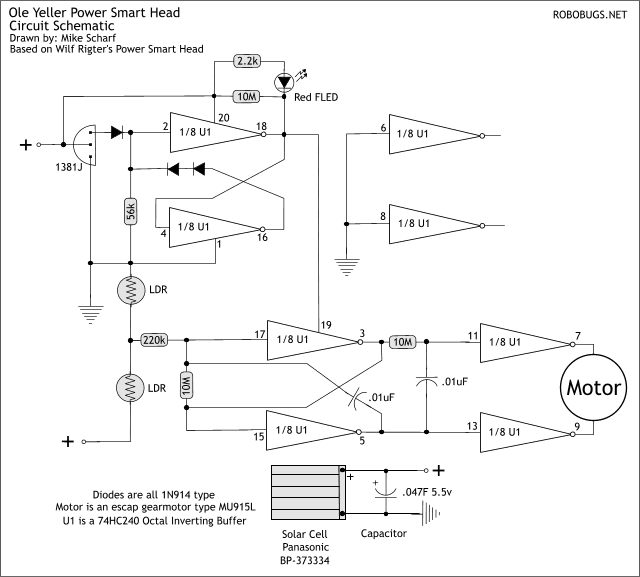
Ole Yeller's Schematic
This is the circuit schematic. For detailed information on the workings, check out Wilf Rigter's article BEAM Heads
101. This article is very detailed and explains how to tune this circuit. The values in this drawing are
the ones that made my power smart head work the best so yours may vary slightly. Watch ROBOBUGS.NET for a copy of Wilf's
article coming soon!

.jpg)
.jpg)
.jpg)
.jpg)